Megger Test For Earthing
Earthing is
the procedure to protect appliances and electrical wiring of a building via
placing a ground rod, connected to the wiring of the building, with very low resistance
in the earth. The purpose is to keep the rod resistance low as compared to the human body to avoid any hazards since we know the current takes the low
resistance path. In case if there is any short the current takes the path via ground
wire to the earth thus preventing any causalities. The earth resistance is different from the circuit resistance
and hence cannot be measured using a multimeter, the equipment designed to
measure the earth resistance is called the megger meter (see Fig 1).
Figure 1 Digital
Megger Meter
A typical
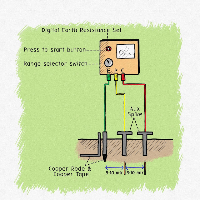
setup for a megger meter is that it makes use of three wires, one of the wires
is connected to the rod in the earthing pit and the other two rods are placed
into the earth at a certain distance which is pre-specified. Usually, one wire is
placed at a distance of 5 meters and the other one at a distance of 10 meters.
Figure 2 Earthing
Setup Via Megger Meter
The rule of thumb is that the resistance of the earthing rod must be less than 1 ohms in case if the resistance of the rod is too high
it indicates that the earthing rod needs to be replaced with a new one. The distance between the earthing electrode and the stakes also depends on the length of the
rod, the following table gives an estimated distance value for rod placement.
|
Earthing Rod Depth (Meters) |
Distance Of Inner Stake From Earthing Rod (Meters) |
Distance Of Outer Stake From Earthing Rod (Meters) |
|
2 |
15 |
25 |
|
3 |
20 |
30 |
|
6 |
25 |
45 |
|
10 |
30 |
50 |
The method discussed here is called the fall of
potential and is most commonly used in housing and sites, there are other
methods which make use of more rods with complex calculations are used for high
resistance sites.


.jpg)


No comments:
Post a Comment